 |
|
THE
SIMPLE ROVERBOT
A Robot Building Project
| | |  |
| |
|
Construction Concepts and Goals
Construct a vehicle powered only by a standard 9 Volt battery that
can avoid obstacles on the left and on the right. The vehicles will have two buttons mounted on
the front (left and right).
For example, if the vehicle hits the right wall, then the vehicle will stop, back up, turn left, and then continue the course.
Vehicle Parts
- Common Components
- Breadboard, wires, 10kW resistor, 1mF capacitor, 0.001mF capacitor,
9-Volt Battery
- Vehicle Chassis
- The chassis (pronounce as 'cha-sE or 'sha-sE) is the supporting frame of a structure.
You can use metal sheets, a pencil box, a toy car, or anything that you like.
[ Image ]
- 1 Caster
- A caster is a wheel mounted in a swivel frame that is commonly used for the support and movement of
furniture and portable equipment. This is one of three wheels on the vehicle.
[ Image ]
- 2 DC Motors with Wheels
- This motor offers 50 in·oz of torque, rotating 360 degrees every 1.6 seconds (38 rpm - just a hair slower than a servo), at 5V, drawing 600mA at stall (free running at 52mA).
[ Image ]
The motors have 90 degree output shafts and a 224:1 gearbox and were purchased from Solarbotics.
(Search for "GM3 Motor".)
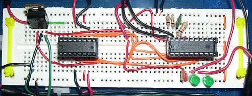
- H-Bridge Chip
- An H-Bridge is a circuit that is constructed from transistors that allows you to change the
direction of rotation of motors or stop the motors.
[ Image ]
- The H-Bridge chip provided is a 754410 chip from Acroname that is great for controlling small motors at roughly 1A peak current.
- The 754410 is a single chip with 2 H-Bridges in it that can handle up to 1A per channel.
- The pin assignments can be found on the PDF Data Sheet provided.
- PIC Microcontroller: 16F84A or 16F819
- Voltage Regulator 7805
- Voltage regulators are needed to reduce the 9-Volts provided by the battery to 5-Volts.
[ Image ]
- These are Fairchild LM7805C regulators.
- The pin assignments can be found on the PDF Data Sheet provided.
- Two Buttons
- These buttons should be mounted on the front of the vehicle to detect obstacles to the left or right.
- These should be wired to the PIC Microcontroller.

Background
Each year students in the electronics course build small vehicles as part of a class project. The goal of this project is to learn how to make the best use of a battery and DC motor in to order
cover 50 feet. In years past, DC motors were used to turn wheels that were in contact with the floor.
In the spring of 2002, we used cooling fans from the inside of old PC computers to propel the vehicle forward.
In 2003 the project will be improved upon again. Instead of an individual project, this is now a team project. New high torque motors will now be used. In addition to this the vehicles will be required to
autonomously detect and avoid obstacles.
There are web pages that document the vehicles built during previous semesters and
the prototype for the 2003 vehicles called the "The SFA Rover". The improvements
in this project were inspired by Chris Dahl's Zaurbot
and the Mars Sojourner Rover.
Scoring
D = Distance traveled in feet in 10 minutes (the maximum distance is 50-feet)
R = 15 if the vehicle successfully demonstrates avoiding an obstacle on the right and 0 if it is not demonstrated
L = 15 if the vehicle successfully demonstrates avoiding an obstacle on the left and 0 if it is not demonstrated
T = -10 each time the vehicle is touched by a team member during the course
Grade = T + L + R + D × 70/(50ft)
Bonus: For each extra left or right obstacle avoided, 2 points of extra credit will be earned for each member of the team.
A maximum of 20 extra points can be earned in this manner.
See your instructor or this PowerPoint file
or this Word file for more information.
Also, this Word document
and this circuit and code template
contain more details about the cicuit and code.
Movies
[ Test Vehicle |
Pencil Box |
All Rovers |
Rover Race ]
Images
[ Pencil Box |
Ampere |
Boolean,
2 |
Diode |
Coulomb |
Electrolyte,
2 ]
Acknowledgements
Thanks to all of my students who participated in this project over the years. The images and inspiration from
Chris Dahl,
Randy Innerarity, and
Heather Dalton and very appreciated.
Related Ideas
Range finders
magenotmeter
water spinkler
stun gun
vision
imaging
LCD
NASA Menu
Robot Menu
Vision Sensors
Parallax BasicStamp
Ordnance Reconnaissance/Removal Device
QURO Biped Robots
Compass
Dan Bruton
Physics 262 and Engineering 215
|